PIONEER S-LA21/X1BR Service Manual

Cover page of PIONEER S-LA21/X1BR Service Manual

Service Manual for PIONEER S-LA21/X1BR, downloadable as a PDF file.

Manual details

  • Immediate download after payment.
  • Delivered as a PDF file.
  • The manual has 3 pages
  • File size: 0.11 MB
  • Available language versions: English
  • Different language versions may vary sligthly in file size and page count.

We guarantee that...

  • our manuals are complete,
  • the manual includes circuit diagrams,
  • our manuals are checked with antivirus,
  • We'll issue refund if the manual is damaged, incomplete or unreadable (our refund policy)

Sample pages

Thumbnail of page 1Thumbnail of page 2Thumbnail of page 3Thumbnail of page 4
Thumbnail of page 5Thumbnail of page 6Thumbnail of page 7
background image
ORDER NO.
PIONEER CORPORATION 4-1, Meguro 1-chome, Meguro-ku, Tokyo 153-8654, Japan
PIONEER ELECTRONICS SERVICE, INC. P.O. Box 1760, Long Beach, CA 90801-1760, U.S.A.
PIONEER EUROPE NV Haven 1087, Keetberglaan 1, 9120 Melsele, Belgium
PIONEER ELECTRONICS ASIACENTRE PTE. LTD. 253 Alexandra Road, #04-01, Singapore 159936
PIONEER CORPORATION 2000
SPEAKER SYSTEM
RRV2415
T­ZZK NOV. 2000 Printed in Japan
S-LA21
X1BR
FOR PRECAUTION OF
REASSEMBLY AND DISASSEMBLY
The woofer is attached to the baffle by 4 internal screws. To
detach it, unfasten those screws.
The midrange is attached to the baffle by 2 internal screws. To
detach it, unfasten those screws.
The tweeter is attached to the baffle by a double sided tape which
peels off the separator. In addition, the outer part is fixed with a
bond.
The tweeter cannot be detached. When exchange the tweeter, do
it with the speaker panel assy.
Speaker Ring and Speaker Grille (Panching Net) is attached to
the baffle by 4 internal screws. To detach it, unfasten those
screws. To detach Speaker Grille (Panching Net), first remove
Speaker Ring. Then remove Speaker Grille (Panching Net).
This product is component of system.
Component
Model
Service manual
Remarks
COMPACT MINI COMPONENT
X-LA21
RRV2412
STEREO CD TUNER
XC-LA21
RRV2413(RRV2392)
STEREO POWER AMPLIFIER
M-LA21
RRV2414(RRV2393)
SPEAKER SYSTEM
S-LA21
RRV2415
This manual.
background image
S-LA21
2
NOTES :
Parts marked by " NSP " are generally unavailable because they are not in our Master Spare Parts List.
The
mark found on some component parts indicates the importance of the safety factor of the part.
Therefore, when replacing, be sure to use parts of identical designation.
PARTS LIST
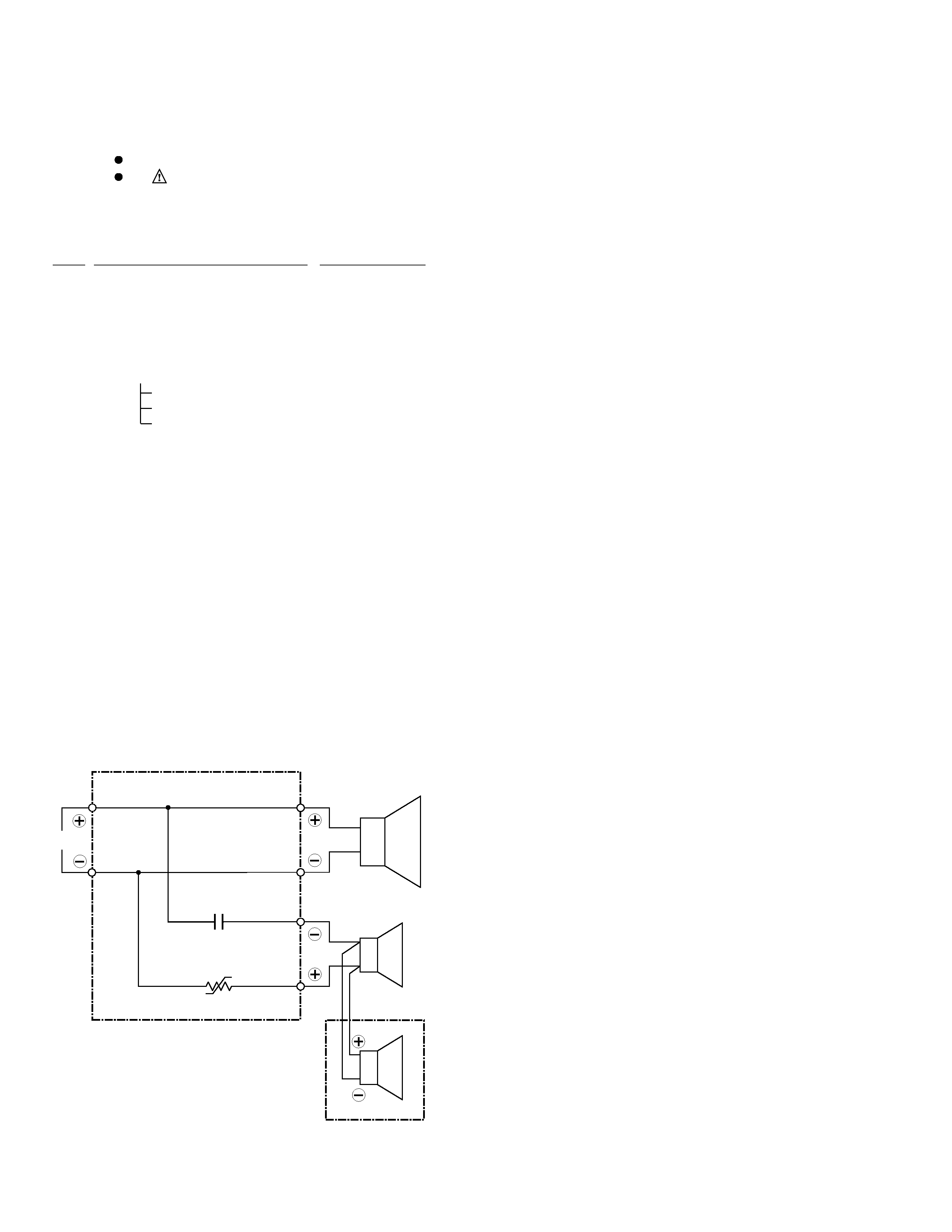
SCHEMATIC DIAGRAM
I N
Red
Black
Red
Woofer
Midrange
Tweeter
Black
Red
Black
Red
Black
2.2
µF
P. SW
Screw (For Mid Unit)
BPZ30P100FNI
Screw (For Woofer Unit)
BPZ30P200FNI
Elect Cap 2.2
00640201063C
Poly Switch
100110020000
NSP
SP Wire
122002020301
Speaker Panel Assy
K--PMTS-SPK
NSP
Tweeter Unit (B26ZA)
129330000000
NSP
Speaker Panel
500PMT322001
NSP
Acoustic Tube
509PMT336000
Mid Unit (E52AP3959D)
131206030010
Woofer Unit (A14LC83)
131557030011
Speaker Ring
509PMT325001
Speaker Grille
607PMT326001
NSP
SPK Box
BR660PMT334000
Acoustic Cushion
700PMT338000
Rubber Foot
700PMT385000
Screw ST4x8 (For Speaker Ring) 720040400080
Screw PMT3 4x55
72304PMT3000
(For Speaker Panel)
Foam Cushion PMT3
801PMT300000
NSP
SPK Label
BR809PMT394040
NSP
Serial No Label (SPK)
809000009000
Mark No.
Description
Part No.
P.SW
P.SW has extreme positive resistance-temperature characteristics. (Less than 0.3W at
the normal temperature). If an abnormal current flows to P.SW due to an excessive
input or unusual signal, P.SW heats up and the resistance rapidly increases. With this
function, the speakers are protected from excessive input or unusual signal. The
resistance value increases even when using a soldering iron for repairing, so allow it to
cool before using.
background image
S-LA21
3
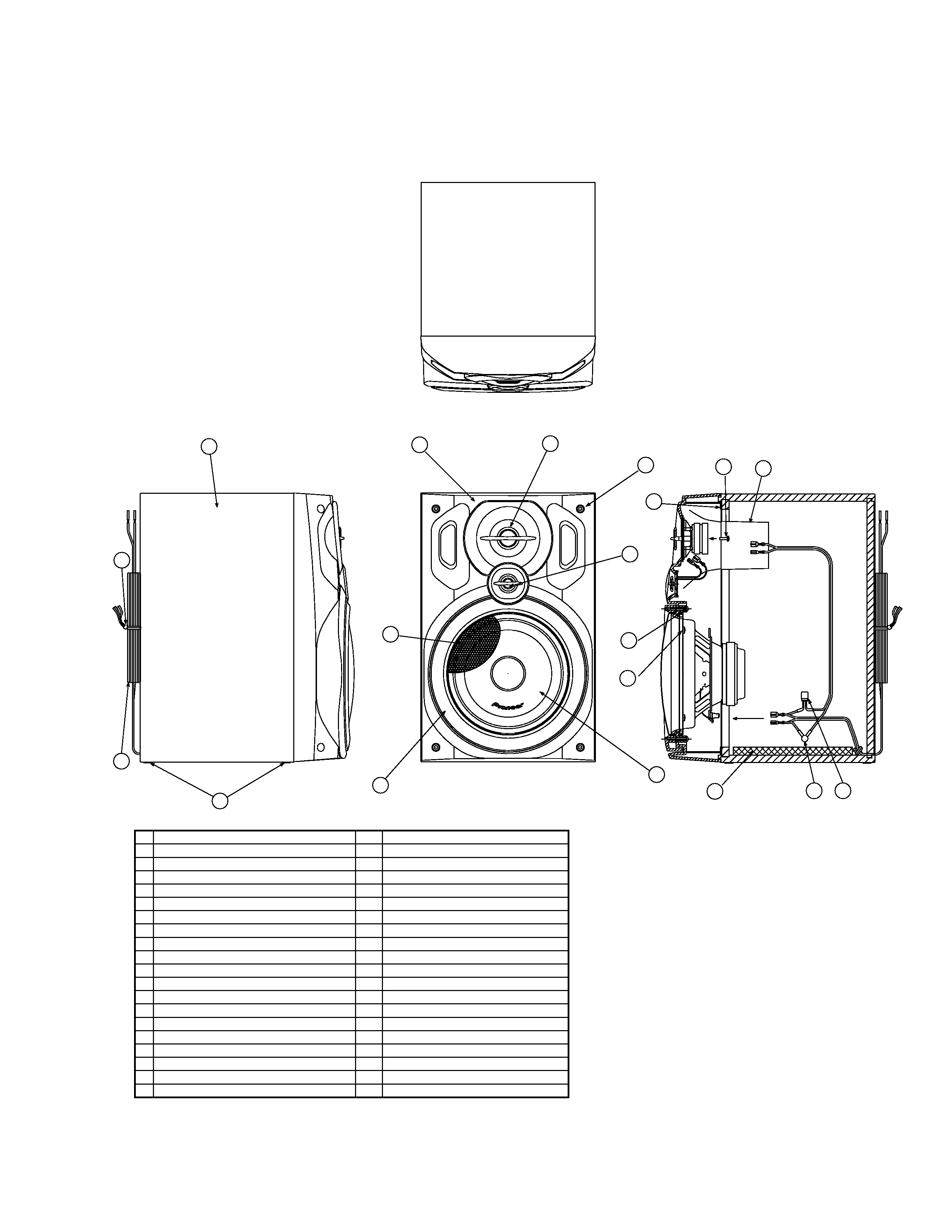
PRODUCT APPEARANCE
5
3
1
2
13
12
14
4
19
11
8
7
6
10
18
9
17
15
16
No.
1
2
3
4
5
6
7
8
9
10
11
12
13
14
15
16
17
18
19
Part name
Speaker Panel
Speaker Box
Speaker Ring
Speaker Grille (Panching Net)
Woofer Unit : A14LC83
Mid Unit : E52AP39-59D
Tweeter : B26ZA
Screw : BPZ30P200FNI
Screw : BPZ30P100FNI
Screw : 4x55 (4mm Hexagon Socket)
Screw : ST4x8
SP Wire
Cord Tie
Rubber Foot
Condenser : 2.2
µF
Poly Switch : RXE020
Acoustic Tube
Foam Cushion
Acoustic Cushion
Num.
1
1
1
1
1
1
1
4
2
4
4
1
1
4
1
1
2
1
1
Remarks

Reviews

There are no reviews of this manual yet.